button on the Window Toolbar.
You may draw, edit, and load your model directly in the model views.
You can draw columns, beams, walls,
and slab edges between existing
There are several graphic editing features that make the creation and
modification of models quite easy. Use the Insert and Modify
Menus or the Drawing Toolbar to utilize these features in the model
view. To create new
All model data is automatically recorded in spreadsheets and the spreadsheets and model views are always in tune (unless you turn this feature off in the Application Settings on the Tools Menu). As you edit a model graphically the spreadsheets are automatically updated and as you make changes in the spreadsheets the model views reflect these changes immediately.
All of the graphical modeling tools may be found on the Drawing Toolbar
shown below. This toolbar may be turned on and off by clicking the button on the Window Toolbar.
RISAFloor Beam Supported Floor:

RISAFloor Concrete Floor Slab:

When you first open a new model in RISAFloor, you are prompted to create a new floor. Once a floor is created a project grid may be useful. This allows you to set up grid lines, which may then be used to define your columns or walls which in turn support the rest of your floor.
Some of the graphic editing options offer more than one way to apply
a modification. This is because there are times when each option
is useful. For example, changing the material of a beam from
Use the following options to specify how you want to choose the items to modify. Choosing Apply Entries to All Selected Items allows you to use the tools on the Selection Toolbar to choose the items you want and then apply the modifications to all selected items at once. Choose Apply Entries by Clicking Items Individually to then click on the items you wish to modify individually. See Graphic Selection for more information on the selection tools.
Note
RISAFloor
provides you with unlimited 'Undo' capability so that you may easily correct
mistakes or just back up to try different possibilities. Simply
click the  button on the RISA Toolbar as many times as you wish to undo your previous actions. The model view and the spreadsheets will visually display
the "undoing". Remember that spreadsheet edits are undone as well.
button on the RISA Toolbar as many times as you wish to undo your previous actions. The model view and the spreadsheets will visually display
the "undoing". Remember that spreadsheet edits are undone as well.
Note
RISAFloor
provides you with unlimited 'Redo' capability so that you may easily redo any actions that were previously undone using the 'Undo' button. Simply
click the  button on the RISA Toolbar as many times as you wish to redo actions that were previously undone. The model view and the spreadsheets will visually display
the “redoing”. Remember that spreadsheet edits are redone as well.
button on the RISA Toolbar as many times as you wish to redo actions that were previously undone. The model view and the spreadsheets will visually display
the “redoing”. Remember that spreadsheet edits are redone as well.
Note
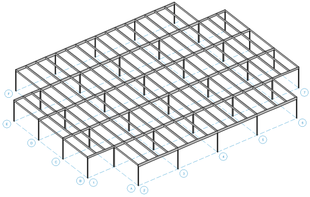
The Project Grid provides convenient snap points for modeling columns and walls in buildings and building-type structures. It also provides a convenient terminology to refer to locations in a model, such as "Grid Intersection C-4". The Project Grid is intended to be a permanent part of the model so unlike the Drawing Grid it is saved with the model.
Click the  button on the RISA Toolbar, or click the Project Grid button on the Data Entry Toolbar
to open the Project Grid Spreadsheet shown below.
button on the RISA Toolbar, or click the Project Grid button on the Data Entry Toolbar
to open the Project Grid Spreadsheet shown below.
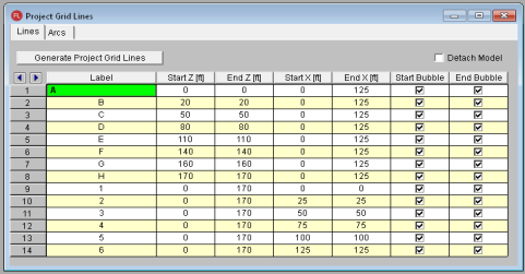
Each Grid Line (as opposed to Grid Arcs) is defined by Start and End coordinates along the X and Z axes. This method of defining grids allows them to be oriented in any direction, including skewed grids or non-parallel grids within the same building.
The columns and walls will move when the project grid is moved. The detach model check-box will allow you to move the project grid lines without moving the model.
Note: The model will move with the associate grid line/arc that moved. For example if you increase the radius of an Arc, the columns on that Arc grid will follow the arc. If you move a Line grid line, the columns/walls will move with that Line grid. This may mean that the column/wall is no longer at the intersection.
The Project Grid Line generator can be accessed using the  button in the Project Grids spreadsheet, or by clicking the
  button on the graphic editing toolbar.
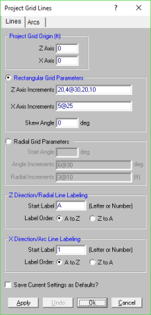
The generator provides the ability to generate an entire grid system at once rather than entering the grids in manually in the project grid spreadsheet.
You may use symbols such as "@", "/" and "," when entering the increments.
The "@" entry may be used to specify multiple, equally spaced, grid increments. For example, if you wanted 7 increments at 10 units each, you would type "7@10" in the increment field.
The "/" entry subdivides a larger increment into smaller equal increments. For example, the entry "12/4" would create 4 increments of 3 units each.
Use commas (",") to enter multiple increments in the increment field. For example, if you wanted to define increments of 3, 4, 7 and 2 units, you could enter "3,4,7,2" in the increment field.
The Apply and Undo buttons provide an easy way to preview a Project Grid before adding one to the model.
Once the project grid is specified and displayed in the model view, it will provide snap points while drawing your model.
Once a Project Grid has been created the grid lines can be moved, or additional grid lines can be created, by double clicking on a grid line in the model view.
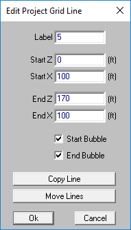
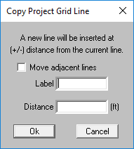
The Copy Line button allows a line to be created by offsetting an existing grid line. If the 'Move adjacent lines' is checked, a new grid line will be created and will shift existing grid lines in the same direction as well. If the 'Move adjacent lines' is unchecked, the new grid line will be created at the offset distance specified, without altering adjacent existing grid lines.
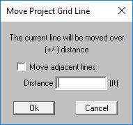
The Move Lines button allows a grid line to be moved by a specified distance. A positive distance will move the line in the positive global direction, while a negative distance will move the line in the opposite direction. If 'Move adjacent lines' is checked, all lines in the same direction will be moved by the same distance as well. This allows for a particular bay in a structure to be made larger/smaller without affecting the other bay sizes.
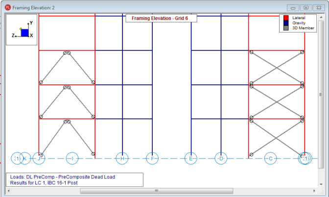
In the RISAFloor interface, below the selection toolbar there is a an  button. This will initiate the Framing Elevation selection tool. The mouse cursor changes to a cross hair icon. Then when you click on a project grid line you will see the elevation view of that project grid line in a new window. The display and label options of this window are based on those in the currently selected model view, but can be changed by clicking on the plot options.
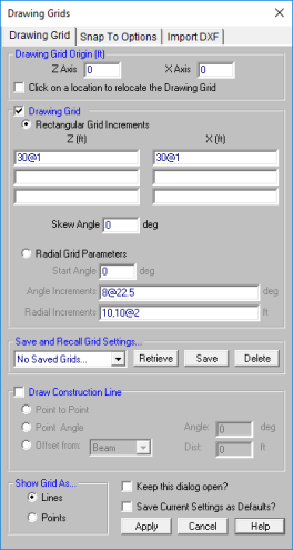
The Drawing Grid is a tool that lets you draw new
Click the  button on the Drawing Toolbar
to open the Drawing Grid Dialog shown above. The display of the Drawing Grid in the current model view may be turned on and off by clicking the
button on the Drawing Toolbar
to open the Drawing Grid Dialog shown above. The display of the Drawing Grid in the current model view may be turned on and off by clicking the  button on the Drawing Toolbar. If the Drawing Toolbar is not visible in the current model view, click the
  button on the Window Toolbar.
You may choose
The Save and Recall Grid Settings... section allows for drawing grids may be saved and recalled for later use. Saved drawing grids are model independent, i.e. when you save a grid, you can reuse it in any other model you are working with in the future. To save a drawing grid, click the Save button after defining the grid. You will be prompted for a name for the drawing grid and it will then be saved and added to the list of grids available for recall. To recall a previously defined drawing grid, select the grid name from the drop down list and click the Retrieve button. If you wish to delete a previously saved drawing grid, select the grid name you want to delete from the drop down list and click the Delete button.
The Show Grid As... section gives the option of displaying the drawing grid as lines from grid point to grid point or simply as a grid of points.
You may save any of the grid information as the default setting so that when you start a new model that information is already there. To do this, simply enter the information that you want to save in the Drawing Grids Dialog, check the Save Current Settings as Defaults box, and then click the OK button.
The rectangular drawing grid is defined by increments in two directions. The Drawing Grid Origin is where you want the grid increments to start. The Rectangular Grid Increments are the distances between the grid points or lines in two global directions.

You may use symbols such as "@", "/" and "," when entering the drawing grid increments.
The "@" entry may be used to specify multiple, equally spaced, grid increments. For example, if you wanted 7 increments at 10 units each, you would type "7@10" in the increment field.
The "/" entry subdivides a larger increment into smaller equal increments. For example, the entry "12/4" would create 4 increments of 3 units each.
Use commas (",") to enter multiple increments in the increment field. For example, if you wanted to define increments of 3, 4, 7 and 2 units, you could enter "3,4,7,2" in the increment field.
Once the drawing grid is specified and displayed in the model view, it will provide snap points while drawing your model.
The rectangular drawing grid can be skewed by specifying a skew angle. This option is available in the Rectangular Grid Increments section of the Drawing Grids Dialog. This skew angle will allow the creation of a regular rectangular drawing grid, but displayed in the model view at the specified angle, inclined from the global axis.
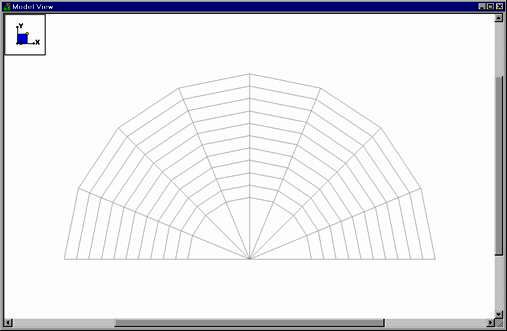
Increments in two polar directions define a radial drawing grid. The Drawing Grid Origin is the point about which the grid will rotate. The default is at the global origin (0,0). The Start Angle defines the angle from the global axis that the first spoke will be drawn. The Angle Increment controls the number and angular spacing of the spokes in the grid. The Radial Increments controls the number and location of the rings in the grid.
The origin of the drawing grid may be specified in two ways. The
first is to enter the exact global coordinates for the origin. This
can be done by entering the values in the X
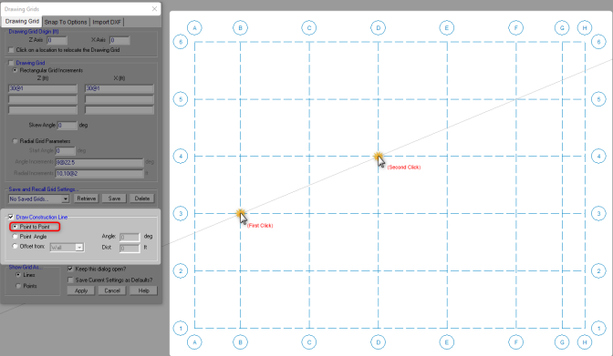
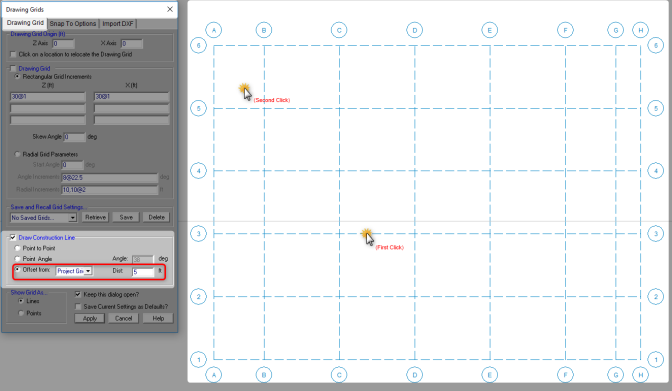
The Draw Construction Line option adds the ability to draw Construction Lines as a type of Drawing Grid. Construction Lines are drawing grid lines that are infinite and allow you to snap to them just as if they were typical drawing grids. Construction Lines can be drawn by either Point to Point, Point Angle or Offset.
Point to Point will draw a construction line that passes through two selected points.
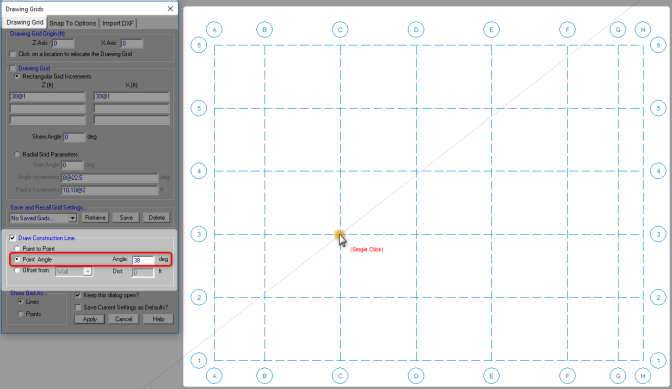
Point Angle will allow the user to define an angle within the dialog and then select a point for construction line to pass through at that specified angle.
Offset will draw a construction line that is parallel and offset by a specified distance to any of three element types chosen by the user; Walls, Beams, or Project Grids. First select the item you would like to reference, then select on which side you would like the construction line to be drawn on.
Snap Points let you draw in the model view without the use of grids. To view or modify the snap point settings, click the button on the Drawing Toolbar and select the Snap To Options tab shown below.
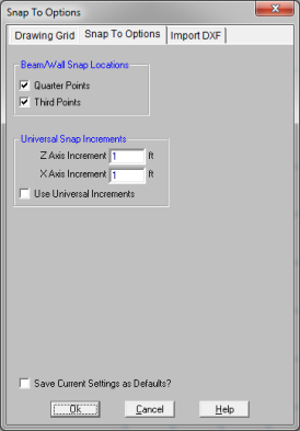
In the Beam Snap Locations section, you can
set the program to automatically snap to the Quarter Points and/or Third Points
of a
The Universal Snap Increments section is used to define a snap grid for
"free" drawing to any incremental location on a plane. To activate this feature, check the Use Universal Increments box. Or, the feature may be toggled on and off in the current model view by clicking the  button on the Drawing Toolbar. If the Drawing Toolbar is not visible in the current model view, click the button on the Window Toolbar.
When snap points
are activated, a red dot or asterisk will appear on your screen as you move your drawing
cursor over one of these points. The exact coordinates of this point,
and whether it is a 1/3 or 1/4 point of a
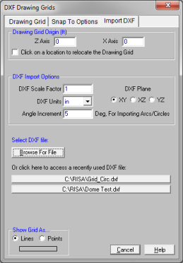
Import DXF lets you import a DXF drawing into the model view as a grid. The DXF image is imported so that you can snap to any point or intersection to aid in the drawing of your model. The DXF Import Drawing Grid supports Lines, Polylines, Circles, Arcs, Polylines with Arcs, and Points.
To Import DXF Drawing Grid:
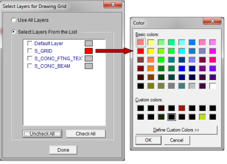
The program will default to use All Layers. Or you can select the color of the grid lines/points by clicking on the color box next to each layer name and select the color.
The origin of the drawing grid may be specified in two ways. The
first is to enter the exact global coordinates for the origin. This
can be done by entering the values in the X
Select the RISA drawing plane for the DXF file shall be placed.
Enter the scale factor that will cause the DXF file to be scaled up or down to full scale. For instance, if you had created a scaled model in AutoCAD at a scale of 1/4"=12", then the appropriate scale factor to produce a full size RISA- model would be 48. The default is 1.0.
Select the DXF drawing plane to import from the DXF file. The DXF file will be flattened to this plane and all lines/points visible from this plane will be imported.
Select the units you used in the CAD model from which you produced the DXF file. The supported DXF units are none, inches, feet, mm, cm, and meters.
The program will break an arc or circle into straight line segments to allow you to snap to them. This indicates the number of degrees the that an imported arc or circle should be broken into.
To Copy Selected Items
Note:
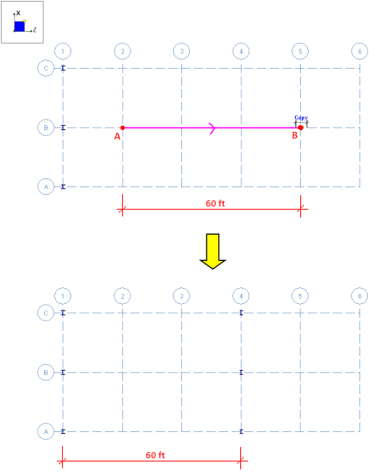
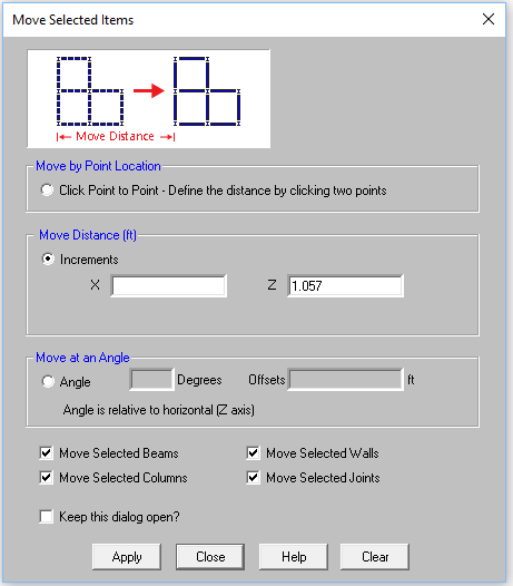
This allows you to copy the selected items by clicking on any two points. The selected items will copy the distance between the two points in the direction of the first to second click.

For example, if you click two points: A then B in the model below, the columns will copy 60 feet in the positive Z direction.
This allows you to copy the selected items by entering in increments in any or all of the global directions. The selected items will copy the increment distance(s) that you have entered.
Use the "@" symbol to specify multiple equal increments. For example specifying "3@10" will give you 3 copies at 10 units apart.
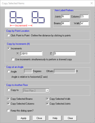
Select the Use increments simultaneously to perform a skewed copy checkbox to combine the orthogonal increments into a single resultant increment vector to copy the elements in a direction other than the three global orthogonal directions.
Select Copy to Another Floor to graphically copy beams, columns, walls and joints on a floor level to another existing floor level.
Note:
There are many Copy Selected checkboxes at the bottom of the dialog to define which elements in the model you wish to copy.
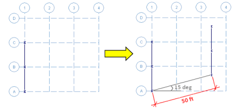
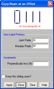
This allows you to copy selected items a certain distance at an input angle. Simply enter the angle (relative to the global Z axis) and the increment and your selected items will be copied in that direction.
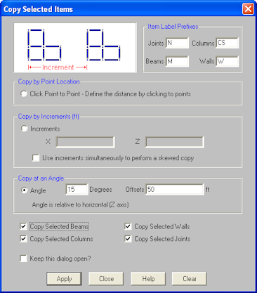
For example, if you enter an angle of 15 degrees and an increment of 50 feet in the model below, it will copy the frame 40 feet at 45 degrees.
The copy to another floor option will duplicate selected beams, columns, walls, and joints on a level to another existing floor level. To use this tool, select these elements in your model view and choose an existing floor level to copy those elements on. The copied elements will be duplicated on the selected floor level. The location of the elements will remain in the same X and Z coordinates as the original floor they were copied from.
Note:
This tool allows you to copy selected
To Move Selected Items
Note:
To Move Selected Items
Note
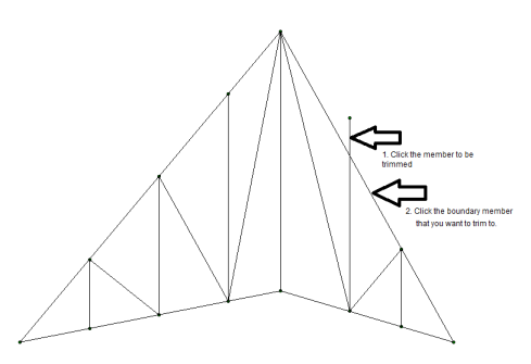
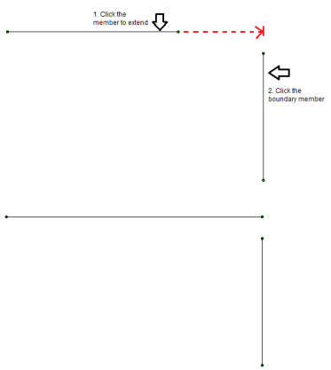
As you modify the model, you may find that you will need to trim or extend a member. The Trim/Extend tool will allow you to modify the ends of any member in relation to another member. This extension is for members only, not walls or plates.
Note
To Perform a Trim
 button.
To Perform an Extend
Click
the Extend button twice or select Extension by clicking the arrow.
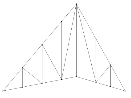
Example 1:
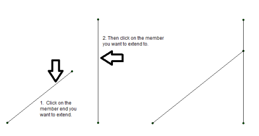
Example 2: The Extend tool can also be used to extend a member to intersection of that member's projected location.
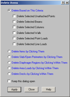
You can delete parts of the model based on the current selection state, or you can click on the items you wish to delete individually. If you accidentally delete something you didn't want deleted, you can use the Undo feature to repair the damage.
If you wish to delete based on the current selection state, you must
use the check boxes to define the criteria the program will use to perform
the deletion. Only items that are selected and that have their check
boxes "checked"
will be deleted. The choices let you delete
Keep in mind that if
you delete
Beam Supported Floors:
Concrete Slab Floor:
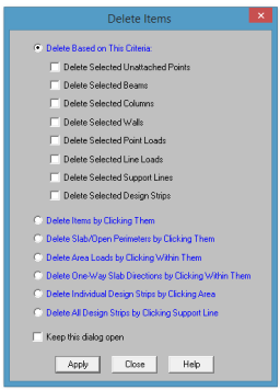
If you request deletion of displayed loads, you'll get exactly that. Any load currently displayed will be deleted. By controlling what loads are displayed via the Loads tab in the Model Display Options Dialog, you can easily delete specific types of loads for particular load categories or load combinations.
Alternatively, you can choose to delete items by clicking on them individually.
Remember to click the Apply button to make your choices active.
To Delete Selected Items
Note
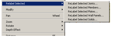
You can use the right-click menu in the program to re-label only the selected items. This is useful when you want all members at a certain elevation to have a prefix which denotes the floor on which it is located.